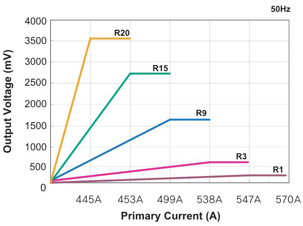
Taehwatrans DC immune CTs show the same level of reading accuracy in AC operating current and in half rectified DC component. What makes our CTs special compared to anti-tampering purpose-only DC immune CTs in the market is that Taehwatrans DC immune CTs are capable of measuring AC and DC component with high accuracy. The actual current loss keeps less than 0.1% and linearity shows less than 0.05% & 0.03 degrees. So even though it has intrinsic high phase displacement, it has an excellent accuracy to satisfy class 0.5 smart meters in addition to measuring multi harmonics in the high accuracy. The characteristics is the supreme linearity throughout the whole dynamic current range and very low current loss.
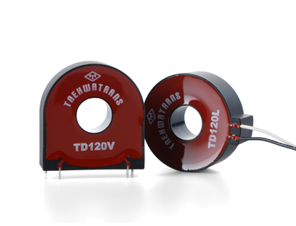
Application
- High end DC immune electronic energy meters
- Measurement of DC components in the AC line
- EV Charger (Stand/Cable)
General Features
- Compliant to IEC 61869-2
- Excellent linearity & precision
- Good performance in DC factor
- Nearly same phase displacement throughout the whole dynamic current.
- High Potential voltage 2.5kV per min.
- UL Recognized
- RoHS compliant
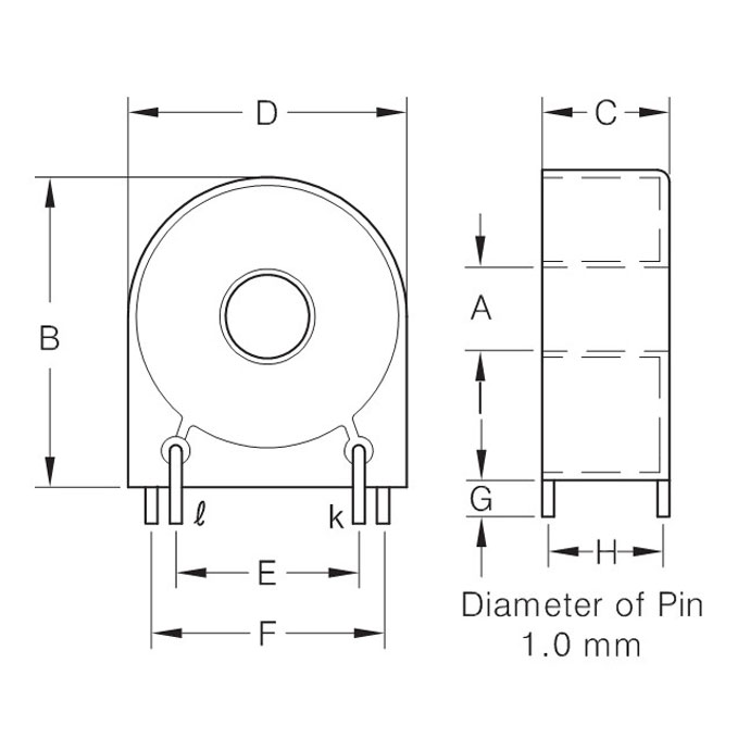
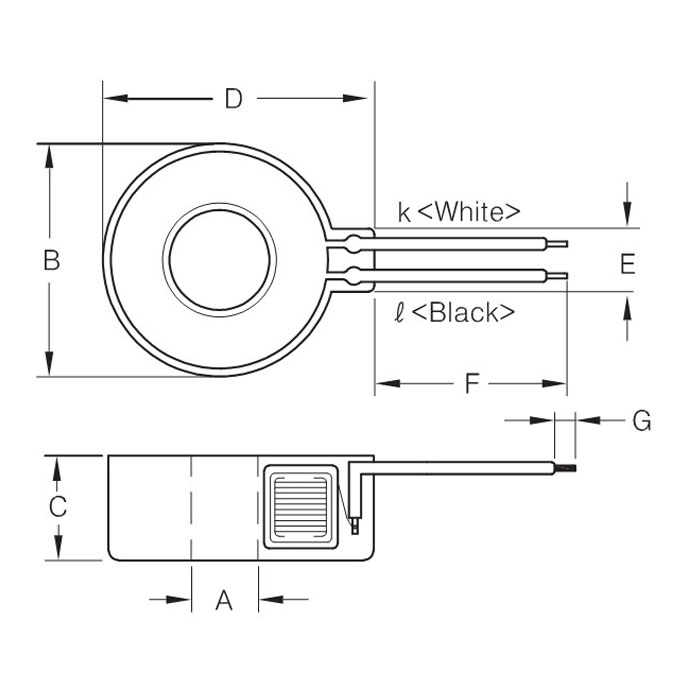
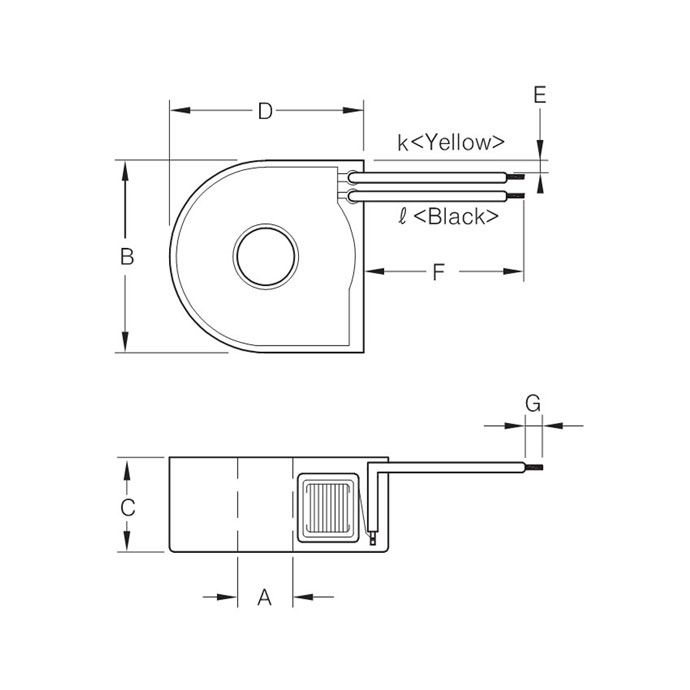
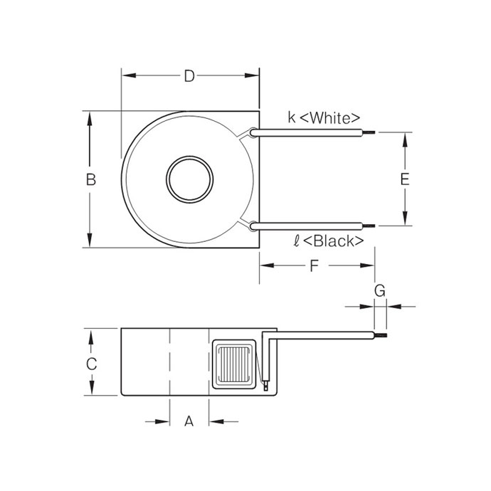
F : 50Hz
| Model NO | Current Ratio | Imax | Idc | DCR(Ω) | Ip = 0.25A | Ip=5A | Linearity @ 0.25-5A range | Dimensions(mm) | ||||||
|---|---|---|---|---|---|---|---|---|---|---|---|---|---|---|
| (±6%) | Ratio Error(%) | Phase Shift (min) | Ratio Error(%) | Phase Shift (min) | Ratio Error | Phase Shfit | Window | Width | Height | Thickness | ||||
| TD35VC | 2500:1 | 72A | 40A | 107 | -0.3±0.5 | 420'±30' | -0.3±0.5 | 417'±30' | 0.1% | 3' | 6.8 | 23.5 | 25.0 | 11.0 |
| TD35L | 2500:1 | 72A | 40A | 107 | -0.3±0.5 | 420'±30' | -0.3±0.5 | 417'±30' | 0.1% | 3' | 6.8 | 26.8 | 23.6 | 11.0 |
| TD40V | 2500:1 | 80A | 40A | 98 | -0.3±0.4 | 250'±20' | -0.3±0.4 | 250'±20' | 0.1% | 2' | 8.9 | 25.3 | 27.5 | 17.0 |
| TD40L | 2500:1 | 80A | 40A | 98 | -0.3±0.4 | 250'±20' | -0.3±0.4 | 250'±20' | 0.1% | 2' | 8.9 | 25.3 | 27.5 | 17.0 |
| TD61L | 2500:1 | 72A | 60A | 61 | -0.3±0.5 | 240'±25' | -0.3±0.5 | 240'±25' | 0.1% | 2' | 8.0 | 31.5 | 30.5 | 15.0 |
| TD120V | 2500:1 | 180A | 120A | 51 | -0.25±0.25 | 240'±25' | -0.25±0.25 | 200'±25' | 0.1% | 1' | 12.9 | 38.0 | 39.3 | 14.0 |
| TD120L | 2500:1 | 180A | 120A | 51 | -0.25±0.25 | 240'±25' | -0.25±0.25 | 200'±25' | 0.1% | 1' | 12.9 | 41.3 | 37.5 | 14.0 |
| TD77V | 2500:1 | 72A | 40A | 85 | ±0.5 | 230'±20' | ±0.5 | 220'±20' | 0.1% | 8' | 6.8 | 23.5 | 25.0 | 11.0 |
| TD77L | 2500:1 | 72A | 40A | 85 | ±0.5 | 230'±20' | ±0.5 | 220'±20' | 0.1% | 8' | 6.9 | 26.8 | 23.6 | 11.0 |
| TD71V/L | 2500:1 | 80A | 40A | 100 | -0.4±0.3 | 720'±50' | -0.4±0.3 | 720'±50' | 0.1% | 5' | 11.2 | 26.9 | 28.7 | 17.0 |
| TD76V | 2500:1 | 180A | 100A | 41 | -0.5±0.5 | 230'±20' | -0.5±0.5 | 230'±20' | 0.1% | 2' | 12.9 | 38.0 | 39.3 | 14.0 |
| TD76L | 2500:1 | 180A | 100A | 41 | -0.5±0.5 | 230'±20' | -0.5±0.5 | 230'±20' | 0.1% | 2' | 12.9 | 41.3 | 37.5 | 14.0 |
* V : PCB Mountable
* L : Lead Wire
F : 50Hz
| Model NO | Current Ratio | Imax | Idc | DCR(Ω) | Ip = 0.25A | Ip=5A | Linearity @ 0.25-5A range | Dimensions(mm) | ||||||
|---|---|---|---|---|---|---|---|---|---|---|---|---|---|---|
| (±6%) | Ratio Error(%) | Phase Shift (min) | Ratio Error(%) | Phase Shift (min) | Ratio Error | Phase Shfit | Window | Width | Height | Thickness | ||||
| TD41L | 2500:1 | 72A | 40A | 149 | -0.03±0.07 | 7'±5' | -0.03±0.07 | 5'±5' | 0.1% | 3' | 8.5 | 31.6 | 30.1 | 18.9 |
| TD121L | 2500:1 | 120A | 120A | 85 | -0.03±0.07 | 7'±5' | -0.03±0.07 | 5'±5' | 0.1% | 3' | 11.0 | 37.8 | 35.7 | 15.6 |
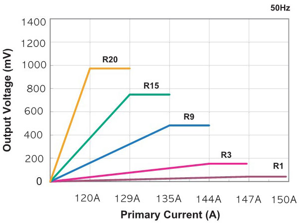
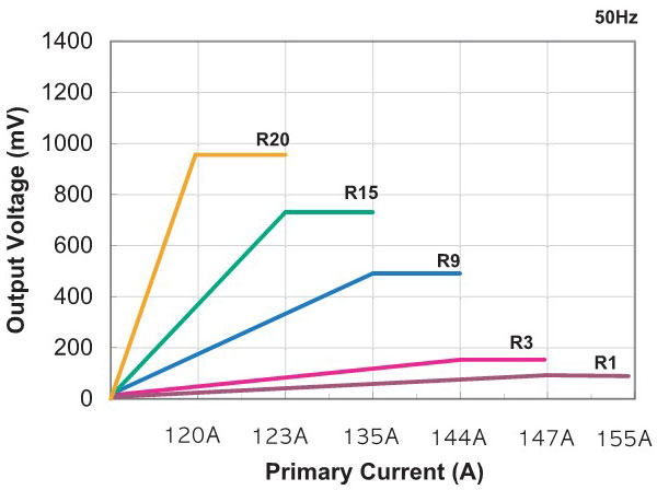
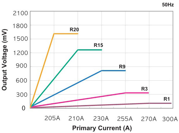
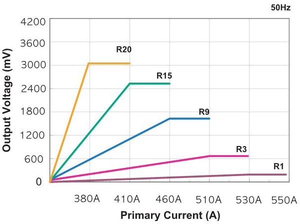
Secondary Burden & Output Voltage.
